Background
This notebook compares a one-dimensional constant-pressure reference model with a two-dimensional, wall-cooled packed-bed model for the gas-phase reaction
The chemistry and the feed follow the fixed-bed reactor exercise: pure A at 293 K with an interstitial velocity of 2 m/s at 1 bar. The 1D reference is solved at a constant 1 bar; the 2D model receives the same inlet molar flux and has its outlet at 1 bar, so its inlet pressure is part of the solution. The 1D reference shows the expected axial conversion, temperature rise and velocity increase when pressure is fixed and the reactor is adiabatic.
The 2D model keeps the same reaction and the same inlet molar flux, but resolves the tube radially, cools it through the wall and solves concentrations, temperature and pressure in one coupled steady residual. The gas flows through a packed bed, so the velocity follows from the local pressure gradient by Darcy’s law. The pressure is then a genuine two-dimensional field: it redistributes the flow radially when the gas near the axis is hotter and expands more than the gas near the wall.
The purpose of the notebook is to show how pressure-velocity coupling fits into the same finite-volume residual structure as species and heat balances, which row determines the pressure, and how to check that the result is right.
from __future__ import annotations

from pathlib import Path
import sys

import matplotlib.pyplot as plt
import numpy as np
import pandas as pd
from scipy.integrate import solve_ivp

for candidate in (Path.cwd(), Path.cwd().parent):
    pymrm_src = candidate / "pymrm" / "src"
    if pymrm_src.exists() and str(pymrm_src) not in sys.path:
        sys.path.insert(0, str(pymrm_src))

import time

from scipy import sparse
from scipy.integrate import cumulative_trapezoid
from scipy.optimize import brentq

from pymrm import (
    NumJac,
    compute_boundary_values,
    construct_convflux_upwind,
    construct_div,
    construct_grad,
    describe_bc,
    newton,
)
from pymrm.checks import check_jacobian, observed_orders, residual_check
Governing Equations
The model is a steady, pseudo-homogeneous description of a packed tube of radius and length in cylindrical coordinates . The unknown field on every cell is
with the concentrations in mol per m of gas. Fluxes are per m of bed cross-section (superficial) and rates per m of bed, which is why the porosity multiplies the rate.
Flow. The superficial velocity follows from Darcy’s law with the viscous (Blake-Kozeny) part of the Ergun equation,
The permeability is isotropic, so the same law gives the axial and the radial velocity. The interstitial velocity is .
Species. With first-order Arrhenius kinetics,
Only radial dispersion is kept; axial dispersion is negligible at this bed length to particle size ratio. is taken constant, a simplification: it is evaluated with a representative mean velocity instead of the local one.
Pressure row. No equation contains as its own unknown, so one balance must be chosen to determine it. Here it is total molar continuity written for the ideal-gas total concentration,
The sum of the three species rows is the same balance for : the same discrete convection-dispersion operator with the same velocity field, the same source and the same total inlet flux. Subtracting the two, the difference satisfies a homogeneous convection-dispersion problem with zero inlet flux, whose only solution is zero. At convergence therefore
in every cell. The ideal gas law is a result of the model, not an imposed row. This only works if the pressure row uses exactly the same fluxes as the species rows, including the dispersive one; the Validation section shows what happens when it does not.
Energy. The energy balance is written in conservative enthalpy form, with the heat-capacity flux of the species fluxes ,
Because and for the given heat capacities, , so this form equals without any artificial source from gas expansion. The face temperature is upwinded by the sign of . The effective radial conductivity has a static and a dynamic (flow) contribution.
Boundary conditions. pymrm writes every boundary condition as
with the outward normal, so the sign of a gradient condition differs between the two ends of an axis.
Inlet, : the molar fluxes , the enthalpy flux at and the total flux are given. The convective operator gets a zero face value there (
{"a": 0, "b": 1, "d": 0}) and the given constant flux is added. Since the flux is given, the pressure has no Dirichlet value at the inlet: ({"a": 1, "b": 0, "d": 0}), and the inlet pressure is part of the solution.Outlet, : (
{"a": 0, "b": 1, "d": p_out}); all convected quantities leave with their cell value ({"outflow": True}). The pressure drop is an output of the model.Axis, : symmetry, for all fields.
Wall, : impermeable, gives , and no dispersive flux. Heat leaves as ; with the outward normal this is , the dictionary
{"a": lam_er, "b": h, "d": h*T_c}.
Parameters and 1D Reference
The reference model uses molar flows per cross-sectional area, , and temperature. At constant pressure,
This is the same variable-velocity constant-pressure formulation used in the fixed-bed exercise.
param = {
    "velocity_in": 2.0,
    "length": 0.5,
    "temperature_in": 293.0,
    "temperature_ref": 293.0,
    "pressure": 101_325.0,
    "x_in": np.array([1.0, 0.0, 0.0]),
    "k0": 1.0e9,
    "activation_energy": 50.0e3,
    "r_gas": 8.314,
    "reaction_enthalpy": -15.0e3,
    "heat_capacity": np.array([100.0, 60.0, 40.0]),
}

stoich = np.array([-1.0, 1.0, 1.0])


def reaction_rate(c_a, temperature, p=param):
    return p["k0"] * np.exp(-p["activation_energy"] / (p["r_gas"] * temperature)) * c_a


def fixed_bed_reference_rhs(z, state, p=param):
    flows = state[:3]
    temperature = state[3]
    total_flow = np.sum(flows)
    c_total = p["pressure"] / (p["r_gas"] * temperature)
    mole_fraction = flows / total_flow
    c_a = mole_fraction[0] * c_total
    rate = reaction_rate(c_a, temperature, p)
    flow_heat_capacity = np.dot(flows, p["heat_capacity"])
    dflows_dz = stoich * rate
    sensible_source = (temperature - p["temperature_ref"]) * np.dot(dflows_dz, p["heat_capacity"])
    dtemperature_dz = ((-p["reaction_enthalpy"]) * rate - sensible_source) / flow_heat_capacity
    return np.r_[dflows_dz, dtemperature_dz]

c_total_in = param["pressure"] / (param["r_gas"] * param["temperature_in"])
flow_in = param["velocity_in"] * c_total_in * param["x_in"]
reference_initial = np.r_[flow_in, param["temperature_in"]]
reference_solution = solve_ivp(
    fixed_bed_reference_rhs,
    (0.0, param["length"]),
    reference_initial,
    method="LSODA",
    dense_output=True,
    rtol=1.0e-10,
    atol=1.0e-12,
)

z_plot = np.linspace(0.0, param["length"], 300)
reference_state = reference_solution.sol(z_plot)
reference_flows = reference_state[:3].T
reference_temperature = reference_state[3]
reference_total_flow = np.sum(reference_flows, axis=1)
reference_c_total = param["pressure"] / (param["r_gas"] * reference_temperature)
reference_mole_fraction = reference_flows / reference_total_flow[:, None]
reference_concentration = reference_mole_fraction * reference_c_total[:, None]
reference_velocity = reference_total_flow / reference_c_total

reference_summary = pd.Series({
    "outlet conversion A": 1.0 - reference_flows[-1, 0] / reference_flows[0, 0],
    "outlet temperature [K]": reference_temperature[-1],
    "outlet velocity [m/s]": reference_velocity[-1],
})
reference_summary
outlet conversion A 1.000000
outlet temperature [K] 443.000000
outlet velocity [m/s] 6.047782
dtype: float642D Model Settings
The 2D model uses the chemistry, the inlet state and the inlet molar flux of the reference calculation: the superficial molar flux carries the same moles per unit bed area as the 1D model with interstitial velocity . The bed and heat-transfer data are needed only for the 2D model. The table below is generated from the settings; its last column states the source of each value, and values marked “assumption” are not given by the exercise and were chosen to be representative for a small catalyst in a gas-cooled tube.
The radial dispersion coefficient uses the radial mass Peclet number of Fahien and Smith with the wall correction, as quoted by Froment and Bischoff,
and the effective radial conductivity is a static part plus a dynamic part with a heat Peclet number of 10,
R_GAS = param["r_gas"]
NU = stoich                                   # (-1, 1, 1)
CP = param["heat_capacity"]                   # J/mol/K; sum(nu * Cp) = 0


def default_params():
    """Settings of the 2D packed-bed model (SI units)."""
    eps, d_p, radius = 0.40, 1.2e-3, 6.0e-3
    p_ref, t_in = param["pressure"], param["temperature_in"]
    n_in = eps * param["velocity_in"] * p_ref / (R_GAS * t_in)   # superficial molar flux, mol/m2/s
    w_flux = CP[0] * n_in                                         # heat-capacity flux, W/m2/K
    u_s_mean = 1.6                                                # representative superficial velocity for D_er, m/s
    pe_m = 10.0 * (1.0 + 19.4 * (d_p / (2 * radius)) ** 2)       # radial mass Peclet (Fahien-Smith)
    pe_h = 10.0                                                   # dynamic radial heat Peclet
    lam_static = 0.15                                             # W/m/K, static bed conductivity
    return dict(
        length=param["length"], radius=radius, eps=eps, d_p=d_p,
        permeability=eps**3 * d_p**2 / (150.0 * (1.0 - eps) ** 2),   # Blake-Kozeny, m2
        kappa_r=1.0,                                                 # K_r / K (isotropic bed)
        mu0=1.85e-5, mu_exp=0.7, t_mu=293.0,                         # mu = mu0 (T / t_mu)^mu_exp
        p_out=p_ref, p_ref=p_ref, t_in=t_in, t_ref=param["temperature_ref"], y_in=param["x_in"],
        n_in=n_in, v_int_in=param["velocity_in"], u_s_mean=u_s_mean,
        k0=param["k0"], ea=param["activation_energy"], dh=param["reaction_enthalpy"],
        pe_m=pe_m, d_er=u_s_mean * d_p / pe_m,
        lam_static=lam_static, lam_er=lam_static + w_flux * d_p / pe_h,
        h_wall=40.0, t_cool=293.0,
        pressure_row_dispersion=True,     # False only for the break row of the ideal-gas check
    )


prm = default_params()
n_z, n_r = 100, 20
parameter_table = pd.DataFrame(
    [
        ("tube length", "L", prm["length"], "m", "exercise"),
        ("tube radius", "R", prm["radius"], "m", "exercise (d_t = 12 mm)"),
        ("bed porosity", "eps", prm["eps"], "-", "de Klerk (2003) correlation at d_t/d_p = 10"),
        ("particle diameter", "d_p", prm["d_p"], "m", "assumption"),
        ("permeability", "K", prm["permeability"], "m2", "Blake-Kozeny (viscous Ergun)"),
        ("viscosity at 293 K", "mu_0", prm["mu0"], "Pa s", "air-like gas (assumption)"),
        ("viscosity exponent, mu ~ T^n", "n", prm["mu_exp"], "-", "air-like gas (assumption)"),
        ("inlet temperature", "T_in", prm["t_in"], "K", "exercise"),
        ("outlet pressure", "p_out", prm["p_out"], "Pa", "exercise (1 bar)"),
        ("inlet interstitial velocity", "v_in", prm["v_int_in"], "m/s", "exercise"),
        ("inlet superficial molar flux", "N_in", prm["n_in"], "mol/m2/s", "eps v_in p/(R T_in), same as 1D"),
        ("pre-exponential factor", "k_0", prm["k0"], "1/s", "exercise"),
        ("activation energy", "E_a", prm["ea"], "J/mol", "exercise"),
        ("reaction enthalpy", "dH_r", prm["dh"], "J/mol", "exercise"),
        ("radial mass Peclet number", "Pe_mr", prm["pe_m"], "-", "Fahien-Smith (Froment-Bischoff)"),
        ("velocity used in D_er", "u_s", prm["u_s_mean"], "m/s", "representative mean (assumption)"),
        ("radial dispersion coefficient", "D_er", prm["d_er"], "m2/s", "u_s d_p / Pe_mr, constant (simplification)"),
        ("dynamic radial heat Peclet number", "Pe_hr", 10.0, "-", "typical packed-bed value (assumption)"),
        ("static radial conductivity", "lam_0", prm["lam_static"], "W/m/K", "assumption"),
        ("effective radial conductivity", "lam_er", prm["lam_er"], "W/m/K", "lam_0 + W d_p / 10"),
        ("overall wall coefficient", "h", prm["h_wall"], "W/m2/K", "assumption (air coolant)"),
        ("coolant temperature", "T_c", prm["t_cool"], "K", "assumption"),
        ("axial cells", "n_z", n_z, "-", "numerical choice"),
        ("radial cells", "n_r", n_r, "-", "numerical choice"),
    ],
    columns=["quantity", "symbol", "value", "unit", "source"],
).set_index("quantity")
parameter_table["value"] = parameter_table["value"].map(lambda v: f"{v:.4g}")
parameter_tablePyMRM Implementation
The model follows the class-based pymrm pattern: build the grid and all constant operators once, evaluate the coupled physics in residual(...), return the residual together with its Jacobian, and let newton solve the steady problem.
Operators. Upwind interpolation matrices for both flow directions (
construct_convflux_upwindwith ), gradients with the boundary dictionaries above (construct_grad) and divergences in Cartesian and cylindrical (construct_divwithnu=0andnu=1). They do not depend on the state.Fluxes. The face velocities come from the pressure gradient and the face temperature. Every convected quantity is upwinded by the sign of its own face velocity, so the discretisation stays well defined if the flow were to reverse during an iteration.
Exact Jacobian. A face flux is (velocity) times (upwinded face value), and the velocity is (mobility of ) times (gradient of ). The product rule applied to these constant matrices gives the exact Jacobian of all transport terms. Only the local reaction source, a block per cell with the full Arrhenius temperature dependence, is differentiated numerically with
NumJac.Scaling. The state is scaled with the inlet concentration, the inlet temperature and a Darcy pressure scale around , and each row with its inlet flux per unit length.
newtonstops on an absolute step norm, so this scaling makes its tolerance meaningful for all five fields.Initial guess. A 1D plug-flow solution with an overall wall coefficient, broadcast over the radius, with a Darcy pressure profile integrated back from the outlet. A step limiter caps the temperature change per iteration and keeps concentrations non-negative, for starts far from the solution.
def sp_diag(v):
    return sparse.diags_array(np.asarray(v, dtype=float).ravel())


class PackedBed2D:
    """Steady wall-cooled packed bed, state (n_z, n_r, 5) = [c_A, c_B, c_C, T, p]."""

    NF = 5            # fields: 0..2 species, 3 temperature, 4 pressure
    IT, IP = 3, 4

    def __init__(self, n_z=100, n_r=20, **overrides):
        self.prm = prm = default_params()
        for key, value in overrides.items():
            if key not in prm:
                raise KeyError(key)
            prm[key] = value
        self.n_z, self.n_r = n_z, n_r
        self.shape = (n_z, n_r, self.NF)
        self.fshape = (n_z, n_r)
        self.n = n_z * n_r
        self._grid()
        self._operators()
        self._scaling()
        self.numjac = NumJac(self.shape)          # 5 x 5 block per cell: local source only

    # ------------------------------------------------------------------ setup
    def _grid(self):
        p = self.prm
        self.z_f = np.linspace(0.0, p["length"], self.n_z + 1)
        self.z_c = 0.5 * (self.z_f[1:] + self.z_f[:-1])
        self.r_f = np.linspace(0.0, p["radius"], self.n_r + 1)
        self.r_c = 0.5 * (self.r_f[1:] + self.r_f[:-1])
        self.area_face_r = np.pi * np.diff(self.r_f**2)          # annulus areas of the axial faces
        self.vol = (np.diff(self.z_f)[:, None] * self.area_face_r[None, :]).ravel()
        self.wall_area = 2 * np.pi * p["radius"] * np.diff(self.z_f)

    def _operators(self):
        p, fs = self.prm, self.fshape
        neumann = {"a": 1.0, "b": 0.0, "d": 0.0}
        # axial transport: the inlet face carries only the given constant fluxes; outflow at z = L
        self.bc_z = ({"a": 0.0, "b": 1.0, "d": 0.0}, {"outflow": True})
        up, _ = construct_convflux_upwind(fs, self.z_f, self.z_c, self.bc_z, v=1.0, axis=0)
        dn, _ = construct_convflux_upwind(fs, self.z_f, self.z_c, self.bc_z, v=-1.0, axis=0)
        self.up_z, self.dn_z = up.tocsr(), (-dn).tocsr()
        self.avg_z = 0.5 * (self.up_z + self.dn_z)
        self.inlet_z = np.zeros((self.n_z + 1, self.n_r))
        self.inlet_z[0, :] = 1.0
        self.inlet_z = self.inlet_z.ravel()                      # marks the inlet faces
        # pressure: dp/dn = 0 at the inlet face (its flux is given), p = p_out at z = L
        self.bc_p_z = (neumann, {"a": 0.0, "b": 1.0, "d": p["p_out"]})
        g, g_bc = construct_grad(fs, self.z_f, self.z_c, self.bc_p_z, axis=0)
        self.grad_z, self.grad_z_bc = g.tocsr(), g_bc.toarray().ravel()
        # radial: symmetry at r = 0, impermeable wall (u_r = 0, no dispersive flux)
        self.bc_r = (neumann, neumann)
        up, _ = construct_convflux_upwind(fs, self.r_f, self.r_c, self.bc_r, v=1.0, axis=1)
        dn, _ = construct_convflux_upwind(fs, self.r_f, self.r_c, self.bc_r, v=-1.0, axis=1)
        self.up_r, self.dn_r = up.tocsr(), (-dn).tocsr()
        self.avg_r = 0.5 * (self.up_r + self.dn_r)
        g, _ = construct_grad(fs, self.r_f, self.r_c, self.bc_r, axis=1)
        self.grad_r = g.tocsr()
        # wall: -lam dT/dr = h (T - T_c); outward normal +r: lam dT/dn + h T = h T_c
        self.bc_t_r = (neumann, {"a": p["lam_er"], "b": p["h_wall"], "d": p["h_wall"] * p["t_cool"]})
        g, g_bc = construct_grad(fs, self.r_f, self.r_c, self.bc_t_r, axis=1)
        self.grad_rt, self.grad_rt_bc = g.tocsr(), g_bc.toarray().ravel()
        self.div_z = construct_div(fs, self.z_f, nu=0, axis=0).tocsr()
        self.div_r = construct_div(fs, self.r_f, nu=1, axis=1).tocsr()
        # selection matrices: field f on the cells <- full flat state
        idx = np.arange(self.n)
        self.sel = [sparse.csr_array((np.ones(self.n), (idx, idx * self.NF + f)), shape=(self.n, self.n * self.NF))
                    for f in range(self.NF)]

    def _scaling(self):
        p = self.prm
        self.c_s = p["p_ref"] / (R_GAS * p["t_in"])
        self.dp_s = p["mu0"] * (p["n_in"] * R_GAS * p["t_in"] / p["p_ref"]) * p["length"] / p["permeability"]
        self.x_off = np.array([0.0, 0.0, 0.0, 0.0, p["p_out"]])
        self.x_scl = np.array([self.c_s, self.c_s, self.c_s, p["t_in"], self.dp_s])
        s_c = p["n_in"] / p["length"]
        s_e = p["n_in"] * (-p["dh"]) / p["length"]
        self.g_scl = 1.0 / np.array([s_c, s_c, s_c, s_e, s_c])
        self.x_scl_flat = np.tile(self.x_scl, self.n)
        self.g_scl_flat = np.tile(self.g_scl, self.n)

    # ------------------------------------------------------------------ physics
    def mobility(self, t_face):
        """K / mu(T) on the faces and its derivative with respect to T."""
        p = self.prm
        t_face = np.maximum(t_face, 100.0)        # guard for wild iterates only
        mob = p["permeability"] / (p["mu0"] * (t_face / p["t_mu"]) ** p["mu_exp"])
        return mob, -p["mu_exp"] * mob / t_face

    def source(self, x):
        """Local terms per cell: [nu_i eps r_A, (-dH) eps r_A, sum(nu) eps r_A]."""
        p = self.prm
        t = np.maximum(x[..., self.IT], 100.0)
        rate = p["eps"] * p["k0"] * np.exp(-p["ea"] / (R_GAS * t)) * x[..., 0]
        return np.stack([NU[0] * rate, NU[1] * rate, NU[2] * rate, -p["dh"] * rate, NU.sum() * rate], axis=-1)

    def flux_terms(self, x):
        """Face fluxes of all five rows and their Jacobians with respect to the flat state."""
        p, E = self.prm, self.sel
        X = x.reshape(self.shape)
        t, pr = X[..., self.IT].ravel(), X[..., self.IP].ravel()
        # Darcy face velocities (superficial); product rule for mobility(T_face) * grad p
        t_z = self.avg_z @ t + self.inlet_z * p["t_in"]
        t_r = self.avg_r @ t
        mob_z, dmob_z = self.mobility(t_z)
        mob_r, dmob_r = self.mobility(t_r)
        gp_z = self.grad_z @ pr + self.grad_z_bc
        gp_r = self.grad_r @ pr
        u_z = -mob_z * gp_z
        u_r = -p["kappa_r"] * mob_r * gp_r
        du_z = -(sp_diag(mob_z) @ self.grad_z @ E[self.IP] + sp_diag(gp_z * dmob_z) @ self.avg_z @ E[self.IT])
        du_r = -p["kappa_r"] * (sp_diag(mob_r) @ self.grad_r @ E[self.IP]
                                + sp_diag(gp_r * dmob_r) @ self.avg_r @ E[self.IT])
        # upwind selection by the sign of u
        pos_z, pos_r = u_z >= 0.0, u_r >= 0.0
        q_z = sp_diag(pos_z) @ self.up_z + sp_diag(~pos_z) @ self.dn_z
        q_r = sp_diag(pos_r) @ self.up_r + sp_diag(~pos_r) @ self.dn_r

        def conv_disp(q, dq, d_er=p["d_er"]):
            """Face fluxes of a cell quantity q (flat) with Jacobian dq (cells x state)."""
            qz, qr = q_z @ q, q_r @ q
            fz = u_z * qz
            fr = u_r * qr - d_er * (self.grad_r @ q)
            dfz = sp_diag(qz) @ du_z + sp_diag(u_z) @ q_z @ dq
            dfr = sp_diag(qr) @ du_r + sp_diag(u_r) @ q_r @ dq - d_er * (self.grad_r @ dq)
            return fz, fr, dfz, dfr

        out = []
        w_z, w_r = np.zeros_like(u_z), np.zeros_like(u_r)
        dw_z, dw_r = 0.0, 0.0
        for i in range(3):                        # species: convection + radial dispersion + inlet flux
            fz, fr, dfz, dfr = conv_disp(X[..., i].ravel(), E[i])
            fz = fz + self.inlet_z * p["y_in"][i] * p["n_in"]
            out.append((fz, fr, dfz, dfr))
            w_z, w_r = w_z + CP[i] * fz, w_r + CP[i] * fr
            dw_z, dw_r = dw_z + CP[i] * dfz, dw_r + CP[i] * dfr
        # energy: W (T_face - T_ref), T_face upwinded by the sign of W; radial conduction
        pos_wz, pos_wr = w_z >= 0.0, w_r >= 0.0
        s_z = sp_diag(pos_wz) @ self.up_z + sp_diag(~pos_wz) @ self.dn_z
        s_r = sp_diag(pos_wr) @ self.up_r + sp_diag(~pos_wr) @ self.dn_r
        tf_z = s_z @ t + self.inlet_z * p["t_in"]
        tf_r = s_r @ t
        ez = w_z * (tf_z - p["t_ref"])
        er = w_r * (tf_r - p["t_ref"]) - p["lam_er"] * (self.grad_rt @ t + self.grad_rt_bc)
        dez = sp_diag(tf_z - p["t_ref"]) @ dw_z + sp_diag(w_z) @ s_z @ E[self.IT]
        der = (sp_diag(tf_r - p["t_ref"]) @ dw_r + sp_diag(w_r) @ s_r @ E[self.IT]
               - p["lam_er"] * (self.grad_rt @ E[self.IT]))
        out.append((ez, er, dez, der))
        # pressure row: total molar continuity on c_t = p / (R T), same operator as the species
        ct = pr / (R_GAS * t)
        dct = sp_diag(1.0 / (R_GAS * t)) @ E[self.IP] - sp_diag(pr / (R_GAS * t**2)) @ E[self.IT]
        fz, fr, dfz, dfr = conv_disp(ct, dct, p["d_er"] if p["pressure_row_dispersion"] else 0.0)
        out.append((fz + self.inlet_z * p["n_in"], fr, dfz, dfr))
        self.last_faces = dict(u_z=u_z, u_r=u_r, w_z=w_z, fluxes=out)
        return out

    # ------------------------------------------------------------------ residual
    def residual_dim(self, x):
        """Dimensional residual div(fluxes) - source and its exact Jacobian."""
        g = np.zeros(self.n * self.NF)
        jac = None
        for f, (fz, fr, dfz, dfr) in enumerate(self.flux_terms(x)):
            g[f::self.NF] = self.div_z @ fz + self.div_r @ fr
            block = self.sel[f].T @ (self.div_z @ dfz + self.div_r @ dfr)
            jac = block if jac is None else jac + block
        s, ds = self.numjac(self.source, x.reshape(self.shape))
        return g - s.ravel(), (jac - ds).tocsc()

    def to_dim(self, xh):
        return (self.x_off + xh.reshape(self.shape) * self.x_scl).ravel()

    def to_hat(self, x):
        return ((x.reshape(self.shape) - self.x_off) / self.x_scl).ravel()

    def residual(self, xh):
        """Scaled residual and Jacobian for newton: g_hat = S_g g(x_off + S_x x_hat)."""
        g, jac = self.residual_dim(self.to_dim(xh))
        return self.g_scl_flat * g, sp_diag(self.g_scl_flat) @ jac @ sp_diag(self.x_scl_flat)

    # ------------------------------------------------------------------ solve
    def initial_guess(self, kind="cooled"):
        """1D plug flow at p_out, broadcast over r, with a Darcy pressure profile.
        kind: 'cooled' (overall U from h and lam_er), 'adiabatic' (U = 0) or 'cold' (no reaction)."""
        p = self.prm
        cooled = kind == "cooled" and p["h_wall"] > 0
        u_w = 1.0 / (1 / p["h_wall"] + p["radius"] / (4 * p["lam_er"])) if cooled else 0.0
        k0 = 0.0 if kind == "cold" else p["k0"]

        def rhs(z, y):
            f, t = y[:3], y[3]
            r = p["eps"] * k0 * np.exp(-p["ea"] / (R_GAS * t)) * f[0] / f.sum() * p["p_out"] / (R_GAS * t)
            return np.r_[NU * r, (-p["dh"] * r - 2 * u_w / p["radius"] * (t - p["t_cool"])) / np.dot(f, CP)]

        sol = solve_ivp(rhs, (0, p["length"]), np.r_[p["n_in"] * p["y_in"], p["t_in"]], method="LSODA",
                        rtol=1e-9, atol=1e-11, dense_output=True)
        f, t = sol.sol(self.z_c)[:3], sol.sol(self.z_c)[3]
        mu = p["mu0"] * (t / p["t_mu"]) ** p["mu_exp"]
        dpdz = mu * f.sum(0) * R_GAS * t / p["p_out"] / p["permeability"]
        z = np.r_[self.z_c, p["length"]]
        pz = p["p_out"] + cumulative_trapezoid(np.r_[dpdz, dpdz[-1]][::-1], -z[::-1], initial=0.0)[::-1][:-1]
        x = np.zeros(self.shape)
        x[..., :3] = (f / f.sum(0) * pz / (R_GAS * t)).T[:, None, :]
        x[..., 3], x[..., 4] = t[:, None], pz[:, None]
        return x.ravel()

    def solve(self, guess="cooled", maxfev=60, max_dt_hat=0.2):
        """Steady monolithic Newton with the exact Jacobian from a 1D guess. The callback
        caps the temperature change per iteration at max_dt_hat * T_in and keeps c_i >= 0."""
        t0 = time.perf_counter()
        x0 = self.to_hat(self.initial_guess(guess))
        prev = [x0.copy()]

        def limit_step(x, g):
            step = x - prev[0].reshape(x.shape)
            d_t = np.abs(step.reshape(-1, self.NF)[:, self.IT]).max()
            if d_t > max_dt_hat:
                x[...] = prev[0].reshape(x.shape) + (max_dt_hat / d_t) * step
            xv = x.reshape(-1, self.NF)
            xv[:, :3] = np.maximum(xv[:, :3], 0.0)
            prev[0] = x.copy()

        res = newton(self.residual, x0, tol=1e-10, maxfev=maxfev, solver="spsolve", callback=limit_step)
        res.cpu = time.perf_counter() - t0
        self.result = res
        self.xh = res.x.ravel()
        self.x = self.to_dim(self.xh).reshape(self.shape)
        self.flux_terms(self.x.ravel())           # store the face fluxes of the solution
        return res

    # ------------------------------------------------------------------ outputs
    def axial_profiles(self):
        """Cup-mixing conversion and temperature and mean interstitial velocity on the axial faces."""
        p, a = self.prm, self.area_face_r
        faces = lambda f: f.reshape(self.n_z + 1, self.n_r)
        fl = self.last_faces["fluxes"]
        f_a = faces(fl[0][0]) @ a
        conversion = 1.0 - f_a / f_a[0]
        t_cup = p["t_ref"] + (faces(fl[3][0]) @ a) / (faces(self.last_faces["w_z"]) @ a)
        v_int = faces(self.last_faces["u_z"]) @ a / a.sum() / p["eps"]
        v_int[0] = p["n_in"] * R_GAS * p["t_in"] / (self.inlet_pressure() @ a / a.sum()) / p["eps"]   # given inlet flux
        p_mean = self.x[..., self.IP] @ a / a.sum()
        return dict(conversion=conversion, t_cup=t_cup, v_int=v_int, p_mean=p_mean)

    def inlet_pressure(self):
        """Inlet face pressure: Darcy over the first half cell at the given inlet flux,
        (p_in - p_1) = c / p_in with u = N_in R T_in / p_in, solved for p_in."""
        p = self.prm
        mu_in = p["mu0"] * (p["t_in"] / p["t_mu"]) ** p["mu_exp"]
        coef = 0.5 * (self.z_f[1] - self.z_f[0]) * mu_in / p["permeability"] * p["n_in"] * R_GAS * p["t_in"]
        p1 = self.x[0, :, self.IP]
        return 0.5 * (p1 + np.sqrt(p1**2 + 4 * coef))

    def outlet(self):
        """Cup-mixing outlet values from the outlet-face fluxes."""
        p = self.prm
        fl = self.last_faces["fluxes"]
        a = self.area_face_r
        out = lambda f: f.reshape(self.n_z + 1, self.n_r)[-1]
        inn = lambda f: f.reshape(self.n_z + 1, self.n_r)[0]
        f_a_in, f_a_out = np.sum(inn(fl[0][0]) * a), np.sum(out(fl[0][0]) * a)
        u_out = out(self.last_faces["u_z"])
        return dict(
            conversion=1.0 - f_a_out / f_a_in,
            t_cup=p["t_ref"] + np.sum(out(fl[3][0]) * a) / np.sum(out(self.last_faces["w_z"]) * a),
            u_s_mean=np.sum(u_out * a) / a.sum(),
            v_int_mean=np.sum(u_out * a) / a.sum() / p["eps"],
            dp=np.sum(self.inlet_pressure() * a) / a.sum() - p["p_out"],
            f_out=sum(np.sum(out(fl[i][0]) * a) for i in range(3)),
            e_out=np.sum(out(fl[3][0]) * a),
        )

    def hot_spot(self):
        iz, ir = np.unravel_index(self.x[..., self.IT].argmax(), self.fshape)
        return dict(t_max=self.x[iz, ir, self.IT], z=self.z_c[iz], r=self.r_c[ir], iz=iz, ir=ir)

    def balances(self):
        """Total molar flow and enthalpy balances from face fluxes and cell sources."""
        p = self.prm
        o = self.outlet()
        s = self.source(self.x).reshape(self.n, self.NF)
        gen_mol, gen_heat = np.sum(s[:, 4] * self.vol), np.sum(s[:, 3] * self.vol)
        t_face_w = compute_boundary_values(self.x[..., self.IT], self.r_f, self.r_c, self.bc_t_r, axis=1)[2]
        q_wall = np.sum(p["h_wall"] * (t_face_w.ravel() - p["t_cool"]) * self.wall_area)
        mol_in = p["n_in"] * p["y_in"].sum() * self.area_face_r.sum()
        return dict(
            mol_in=mol_in, mol_gen=gen_mol, mol_out=o["f_out"],
            mol_rel=(mol_in + gen_mol - o["f_out"]) / mol_in,
            heat_gen=gen_heat, heat_out=o["e_out"], heat_wall=q_wall,
            heat_rel=(gen_heat - o["e_out"] - q_wall) / gen_heat,
        )

    def ideal_gas_error(self):
        """max over the cells of |sum(c_i) R T / p - 1|."""
        c_sum = self.x[..., :3].sum(axis=-1)
        c_eos = self.x[..., self.IP] / (R_GAS * self.x[..., self.IT])
        return np.max(np.abs(c_sum / c_eos - 1.0))
The boundary dictionaries, written out as the equations they impose with describe_bc. Note the sign of the gradient term at the lower ends, where the outward normal points in the negative coordinate direction.
model = PackedBed2D(n_z=n_z, n_r=n_r)
print("species, temperature (axial transport):")
print(describe_bc(model.bc_z, model.z_f, axis_name="z", var="c_i"))
print("pressure (axial):")
print(describe_bc(model.bc_p_z, model.z_f, axis_name="z", var="p"))
print("species and pressure (radial), phi = c_i or p:")
print(describe_bc(model.bc_r, model.r_f, axis_name="r", var="phi"))
print("temperature (radial):")
print(describe_bc(model.bc_t_r, model.r_f, axis_name="r", var="T"))
species, temperature (axial transport):
lower (z=0, outward normal -z): 0*dc_i/dz + 1*c_i = 0 [Dirichlet]
upper (z=0.5, outward normal +z): outflow, face value = adjacent cell value, zero diffusive flux
pressure (axial):
lower (z=0, outward normal -z): -1*dp/dz + 0*p = 0 [Neumann]
upper (z=0.5, outward normal +z): 0*dp/dz + 1*p = 101325 [Dirichlet]
species and pressure (radial), phi = c_i or p:
lower (r=0, outward normal -r): -1*dphi/dr + 0*phi = 0 [Neumann]
upper (r=0.006, outward normal +r): 1*dphi/dr + 0*phi = 0 [Neumann]
temperature (radial):
lower (r=0, outward normal -r): -1*dT/dr + 0*T = 0 [Neumann]
upper (r=0.006, outward normal +r): 0.54931*dT/dr + 40*T = 11720 [Robin]
result = model.solve()
check = residual_check(model.residual, model.xh)
print(f"success = {result.success}, Newton iterations = {result.nit}, CPU time {result.cpu:.2f} s")
print(f"backward error = {check['backward_error']:.1e} (ok = {check['ok']})")
success = True, Newton iterations = 6, CPU time 0.57 s
backward error = 1.2e-13 (ok = True)
Results
The table compares the 2D wall-cooled bed with the 1D adiabatic constant-pressure reference. The 2D outlet values are cup-mixing averages computed from the outlet face fluxes, the velocity is the area-averaged interstitial velocity at the outlet, and the pressure drop is the area-averaged inlet pressure minus .
Wall cooling removes a large part of the reaction heat: the outlet is much colder than in the adiabatic 1D model, and the conversion is slightly lower but still almost complete. The gas expands less because it is colder, so the outlet velocity is lower. The hot spot lies on the axis, where the heat has the longest path to the wall.
out = model.outlet()
hot = model.hot_spot()
t_ref_max = reference_temperature.max()
summary_table = pd.DataFrame(
    {
        "1D reference (adiabatic, constant p)": [
            f"{reference_summary['outlet conversion A']:.4f}",
            f"{reference_summary['outlet temperature [K]']:.2f}",
            f"{reference_summary['outlet velocity [m/s]']:.4f}",
            "0 (imposed)",
            f"{t_ref_max:.2f}",
            "none, T rises monotonically",
        ],
        "2D wall-cooled Darcy model": [
            f"{out['conversion']:.4f}",
            f"{out['t_cup']:.2f}",
            f"{out['v_int_mean']:.4f}",
            f"{out['dp']:.0f}",
            f"{hot['t_max']:.2f}",
            f"{hot['z']:.3f} (r = {1e3 * hot['r']:.2f} mm)",
        ],
    },
    index=["outlet conversion A", "outlet temperature [K]", "outlet interstitial velocity [m/s]",
           "pressure drop [Pa]", "maximum temperature [K]", "position of maximum, z [m]"],
)
summary_tableprof = model.axial_profiles()
ref_f = reference_solution.sol(model.z_f)
ref_conv = 1.0 - ref_f[0] / ref_f[0, 0]
ref_t = ref_f[3]
ref_v = ref_f[:3].sum(0) * R_GAS * ref_t / param["pressure"]
fig, axes = plt.subplots(2, 2, figsize=(11, 7.5), sharex=True)
axes[0, 0].plot(model.z_f, prof["conversion"], label="2D cup average")
axes[0, 0].plot(model.z_f, ref_conv, "--", label="1D reference")
axes[0, 0].set_ylabel("conversion of A [-]")
axes[0, 1].plot(model.z_f, prof["t_cup"], label="2D cup average")
axes[0, 1].plot(model.z_c, model.x[:, 0, 3], ":", label="2D on the axis")
axes[0, 1].plot(model.z_f, ref_t, "--", label="1D reference")
axes[0, 1].set_ylabel("T [K]")
axes[1, 0].plot(model.z_f, prof["v_int"], label="2D area average")
axes[1, 0].plot(model.z_f, ref_v, "--", label="1D reference")
axes[1, 0].set_ylabel("interstitial velocity [m s$^{-1}$]")
axes[1, 1].plot(model.z_c, prof["p_mean"] - prm["p_out"], label="2D area average")
axes[1, 1].axhline(0.0, ls="--", color="C1", label="1D reference (constant p)")
axes[1, 1].set_ylabel("$p - p_{out}$ [Pa]")
for ax in axes.ravel():
ax.grid(True)
ax.legend(fontsize=8)
for ax in axes[1]:
ax.set_xlabel("z [m]")
plt.tight_layout()
plt.show()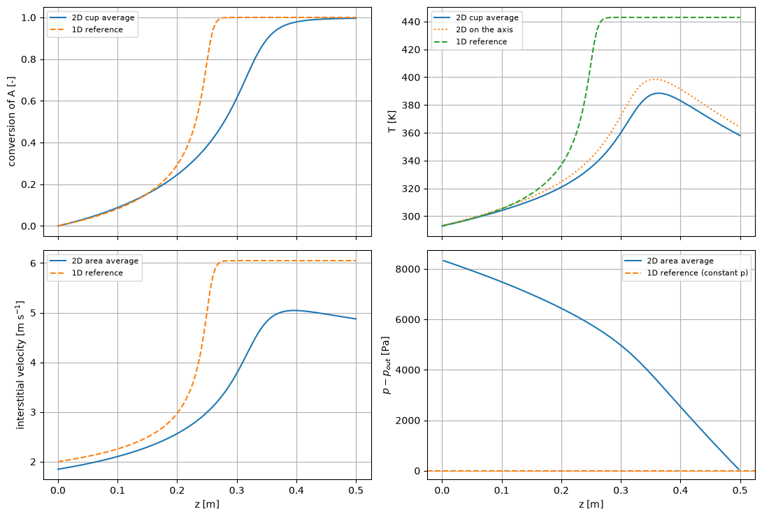
The 2D fields show the radial structure that a 1D model cannot represent. The velocity panel shows the superficial axial velocity on the axial faces. It is almost uniform over the radius, as expected in a packed bed, but not exactly: where the axis is hotter the gas there is more viscous and expands more, and the pressure field redistributes the flow.
uz_faces = model.last_faces["u_z"].reshape(model.n_z + 1, model.n_r)
fields_2d = [
    (model.z_c, model.x[..., 0], "$c_A$ [mol m$^{-3}$]"),
    (model.z_c, model.x[..., 3], "$T$ [K]"),
    (model.z_c, model.x[..., 4] - prm["p_out"], "$p - p_{out}$ [Pa]"),
    (model.z_f[1:], uz_faces[1:], "$u_z$ (superficial) [m s$^{-1}$]"),
]
fig, axes = plt.subplots(2, 2, figsize=(12, 7.2), sharex=True, sharey=True)
for ax, (zz, field_2d, title) in zip(axes.ravel(), fields_2d):
    mesh_z, mesh_r = np.meshgrid(zz, model.r_c, indexing="ij")
    pcm = ax.pcolormesh(mesh_z, 1e3 * mesh_r, field_2d, shading="nearest")
    ax.set_title(title)
    fig.colorbar(pcm, ax=ax)
for ax in axes[1]:
    ax.set_xlabel("z [m]")
for ax in axes[:, 0]:
    ax.set_ylabel("r [mm]")
plt.tight_layout()
plt.show()

print(f"minimum axial velocity u_z = {uz_faces[1:].min():.3f} m/s (no backflow), "
      f"max |u_r| = {np.abs(model.last_faces['u_r']).max():.1e} m/s")
print(f"largest radial pressure difference = {np.ptp(model.x[..., 4], axis=1).max():.2f} Pa "
      f"(axial pressure drop {out['dp']:.0f} Pa)")
print(f"at the hot spot: u_z wall / u_z axis = {uz_faces[hot['iz'] + 1, -1] / uz_faces[hot['iz'] + 1, 0]:.3f}")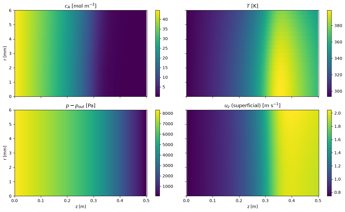
minimum axial velocity u_z = 0.743 m/s (no backflow), max |u_r| = 4.8e-03 m/s
largest radial pressure difference = 0.25 Pa (axial pressure drop 8346 Pa)
at the hot spot: u_z wall / u_z axis = 1.034
z_probe = [0.1, hot["z"], 0.5]
fig, axes = plt.subplots(1, 2, figsize=(11, 4))
for zp in z_probe:
    iz = np.argmin(np.abs(model.z_c - zp))
    lab = f"z = {model.z_c[iz]:.4f} m"
    axes[0].plot(1e3 * model.r_c, model.x[iz, :, 3], "o-", ms=3, label=lab)
    axes[1].plot(1e3 * model.r_c, model.x[iz, :, 0], "o-", ms=3, label=lab)
    print(f"{lab}: T axis {model.x[iz, 0, 3]:.1f} K, wall cell {model.x[iz, -1, 3]:.1f} K; "
          f"c_A axis {model.x[iz, 0, 0]:.2f}, wall cell {model.x[iz, -1, 0]:.2f} mol/m3")
axes[0].set_ylabel("T [K]")
axes[1].set_ylabel("$c_A$ [mol m$^{-3}$]")
for ax in axes:
    ax.set_xlabel("r [mm]")
    ax.grid(True)
    ax.legend(fontsize=8)
plt.tight_layout()
plt.show()
z = 0.0975 m: T axis 305.2 K, wall cell 303.2 K; c_A axis 35.89, wall cell 36.23 mol/m3
z = 0.3575 m: T axis 398.6 K, wall cell 379.7 K; c_A axis 0.74, wall cell 1.59 mol/m3
z = 0.4975 m: T axis 364.8 K, wall cell 352.2 K; c_A axis 0.05, wall cell 0.07 mol/m3
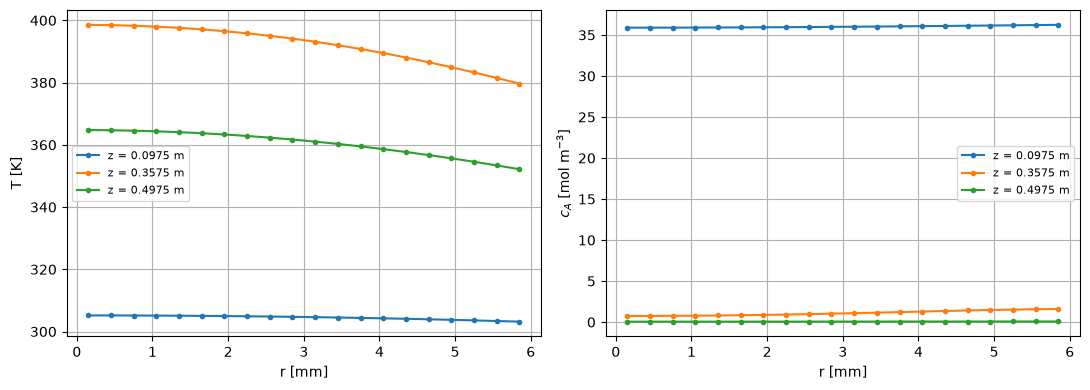
The radial profiles are taken in the cells nearest to = 0.1 m, at the hot spot and at the outlet. Near the inlet the reaction has hardly started and the profiles are nearly flat, within about 2 K. At the hot spot the axis is about 19 K hotter than the cell next to the wall, and is lowest on the axis, where the reaction is fastest. At the outlet A is almost used up and the temperature relaxes towards the coolant.
Validation
A converged Newton iteration only proves that the discrete equations are satisfied. The checks below test that they are the right equations and that the grid resolves them: residual and Jacobian, conservation from the face fluxes, the ideal gas law as a consequence of the pressure row (with a break row that shows the check can fail), the adiabatic limit against the 1D reference, a second independent route to the pressure drop, and grid refinement.
Residual and Jacobian. residual_check evaluates the backward error of the converged state. check_jacobian compares the assembled Jacobian with central differences on a small grid, in a state perturbed away from the solution so that the radial velocity has both signs.
check = residual_check(model.residual, model.xh)
print(f"backward error {check['backward_error']:.1e}, max |g_hat| {check['max_abs_residual']:.1e}, ok = {check['ok']}")

small = PackedBed2D(n_z=10, n_r=6)
xh = small.to_hat(small.initial_guess("cooled")) * (1 + 0.03 * np.sin(np.arange(small.n * 5)))
xh[4::5] += 0.2 * np.cos(np.arange(small.n))     # radial pressure differences: u_r of both signs
print(f"Jacobian against central differences: max relative error "
      f"{check_jacobian(small.residual, xh)['max_rel_error']:.1e}")
backward error 1.2e-13, max |g_hat| 5.1e-08, ok = True
Jacobian against central differences: max relative error 1.2e-06
Conservation. The total molar flow and the enthalpy are balanced with the face fluxes that the residual uses, not with interpolated fields: moles in plus moles produced must equal moles out, and the heat released by the reaction must leave either with the gas or through the wall.
bal = model.balances()
print(f"molar flow:  in {bal['mol_in']:.6e} + produced {bal['mol_gen']:.6e} = out {bal['mol_out']:.6e} mol/s, "
      f"relative error {abs(bal['mol_rel']):.1e}")
print(f"enthalpy:    released {bal['heat_gen']:.2f} W = out with the gas {bal['heat_out']:.2f} W "
      f"+ to the wall {bal['heat_wall']:.2f} W, relative error {abs(bal['heat_rel']):.1e}")
molar flow: in 3.763408e-03 + produced 3.748637e-03 = out 7.512045e-03 mol/s, relative error 1.7e-13
enthalpy: released 56.23 W = out with the gas 24.47 W + to the wall 31.76 W, relative error 3.7e-14
Ideal gas law as a result. The pressure row makes hold in every cell to round-off. The break row removes only the dispersive term from the pressure row. The species rows still have it, the two operators now differ and the ideal gas law is violated by a few percent. A check that cannot fail proves nothing; this one fails when the pressure row is not the sum of the species rows.
print(f"model:     max |sum(c_i) R T / p - 1| = {model.ideal_gas_error():.1e}")
broken = PackedBed2D(n_z=n_z, n_r=n_r, pressure_row_dispersion=False)
broken.solve()
print(f"break row: max |sum(c_i) R T / p - 1| = {broken.ideal_gas_error():.1e} "
      f"(pressure row without -D_er dc_t/dr)")
model: max |sum(c_i) R T / p - 1| = 6.7e-16
break row: max |sum(c_i) R T / p - 1| = 2.6e-02 (pressure row without -D_er dc_t/dr)
Adiabatic limit. With the solution must be radially uniform and must reproduce the 1D plug-flow reference: at full conversion the outlet temperature is fixed by the energy balance, and the outlet velocity by the ideal gas law at . The small velocity difference is a first-order discretisation error: the upwind face concentration at the outlet is the value in the last cell, where the pressure is higher than by half a cell of pressure drop, so the gas there is slightly denser and the outlet face velocity slightly lower. The cell below prints both relative differences.
adiabatic = PackedBed2D(n_z=n_z, n_r=n_r, h_wall=0.0)
res_a = adiabatic.solve("adiabatic")
out_a = adiabatic.outlet()
print(f"h = 0: success = {res_a.success}, Newton iterations {res_a.nit}, "
      f"radial T span {np.ptp(adiabatic.x[..., 3], axis=1).max():.1e} K")
print(f"outlet conversion  2D {out_a['conversion']:.6f}   1D {reference_summary['outlet conversion A']:.6f}")
print(f"outlet T [K]       2D {out_a['t_cup']:.2f}       1D {reference_summary['outlet temperature [K]']:.2f}")
print(f"outlet v_int [m/s] 2D {out_a['v_int_mean']:.4f}       1D {reference_summary['outlet velocity [m/s]']:.4f}")
rel_v = out_a["v_int_mean"] / reference_summary["outlet velocity [m/s]"] - 1.0
rel_p = adiabatic.x[-1, :, 4].mean() / prm["p_out"] - 1.0
print(f"relative velocity difference {rel_v:.1e}; last-cell pressure above p_out, relative {rel_p:.1e}")
h = 0: success = True, Newton iterations 7, radial T span 2.2e-12 K
outlet conversion 2D 1.000000 1D 1.000000
outlet T [K] 2D 443.00 1D 443.00
outlet v_int [m/s] 2D 6.0426 1D 6.0478
relative velocity difference -8.6e-04; last-cell pressure above p_out, relative 8.6e-04
Second route to the pressure drop. For the 2D model reduces to a 1D plug-flow model with Darcy flow, which can be integrated as an ODE for the molar flows, the temperature and the pressure. The inlet pressure is not known, so it is found by shooting until . This route shares no code with the finite-volume model. The gap between the two pressure drops is a discretisation error of the first-order upwind scheme, so it must shrink roughly by half each time the axial grid is refined.
def reference_1d_darcy(p):
    """Adiabatic plug flow with Darcy pressure drop and mu(T), superficial basis,
    shooting on the inlet pressure so that p(L) = p_out."""
    def rhs(z, y):
        f, t, pr = y[:3], y[3], y[4]
        c_a = f[0] / f.sum() * pr / (R_GAS * t)
        r = p["eps"] * p["k0"] * np.exp(-p["ea"] / (R_GAS * t)) * c_a
        u = f.sum() * R_GAS * t / pr
        mu = p["mu0"] * (t / p["t_mu"]) ** p["mu_exp"]
        return np.r_[NU * r, -p["dh"] * r / np.dot(f, CP), -mu * u / p["permeability"]]

    run = lambda p_in: solve_ivp(rhs, (0, p["length"]), np.r_[p["n_in"] * p["y_in"], p["t_in"], p_in],
                                 method="LSODA", rtol=1e-10, atol=1e-10)
    p_in = brentq(lambda q: run(q).y[4, -1] - p["p_out"], p["p_out"], 2 * p["p_out"], xtol=1e-6)
    return p_in - p["p_out"]


dp_ode = reference_1d_darcy(adiabatic.prm)
print(f"1D Darcy ODE (shooting): pressure drop {dp_ode:.0f} Pa")
print(f"2D model, h = 0, n_r = {n_r}:")
for nz in (50, 100, 200):
    m_a = adiabatic if nz == n_z else PackedBed2D(n_z=nz, n_r=n_r, h_wall=0.0)
    if nz != n_z:
        m_a.solve("adiabatic")
    dp_2d = m_a.outlet()["dp"]
    print(f"  n_z = {nz:3d}: pressure drop {dp_2d:.0f} Pa, gap to the ODE {dp_2d - dp_ode:.0f} Pa")
1D Darcy ODE (shooting): pressure drop 11610 Pa
2D model, h = 0, n_r = 20:
  n_z =  50: pressure drop 11947 Pa, gap to the ODE 338 Pa
  n_z = 100: pressure drop 11775 Pa, gap to the ODE 165 Pa
n_z = 200: pressure drop 11692 Pa, gap to the ODE 82 Pa
Grid refinement. Both directions are refined together by a factor 2. The first-order upwind scheme should give an observed order close to 1 for the outlet cup temperature; observed_orders also returns a Richardson estimate of the grid-converged value and of the error of the finest grid.
def outlet_temperature(k):
    m_k = PackedBed2D(n_z=25 * k, n_r=5 * k)
    m_k.solve()
    return m_k.outlet()["t_cup"]


orders = observed_orders(outlet_temperature, [2, 4, 8])
print("grids (n_z, n_r) = (50, 10), (100, 20), (200, 40)")
print(f"outlet cup temperature {np.round(orders['values'], 3)} K")
print(f"observed order {orders['orders'][0]:.2f}, extrapolated {orders['extrapolated']:.2f} K "
      f"(error estimate of the finest grid {orders['error_estimate']:.2f} K)")
grids (n_z, n_r) = (50, 10), (100, 20), (200, 40)
outlet cup temperature [357.105 358.017 358.481] K
observed order 0.98, extrapolated 358.96 K (error estimate of the finest grid 0.48 K)
Modelling notes
Why Darcy flow, and why pressure is a 2D field. In an empty tube the laminar velocity profile is fixed by the wall and the axial pressure gradient; a model that prescribes a parabolic profile has no use for a radial pressure. In a packed bed the resistance comes from the particles, and the velocity follows the local pressure gradient in every direction. The pressure is then a genuine two-dimensional unknown: when the gas on the axis heats up and expands, its viscosity and volume flow rise, the pressure redistributes, and part of the flow moves towards the colder wall region. The streamtubes are not independent. The flow profile is almost flat, even near the wall, so there are no stagnant cells and no backflow; the minimum axial velocity and the radial pressure differences printed in the Results section confirm this.
Why a steady Newton solve with the exact Jacobian works. A model with a prescribed parabolic velocity profile leaves nearly stagnant cells at the wall, which typically forces pseudo-time stepping and a lagged Arrhenius factor. In the packed bed every cell is flushed, the transport operator is well conditioned, and the only strong nonlinearity is the Arrhenius term. With the exact Jacobian, including , Newton converges quadratically from the 1D cooled guess. The steady state is unique for these settings: starts from a cold, non-reacting guess and from the adiabatic guess reach the same solution.
for guess in ("cold", "adiabatic"):
    m_g = PackedBed2D(n_z=n_z, n_r=n_r)
    r_g = m_g.solve(guess)
    print(f"start '{guess}': success = {r_g.success}, Newton iterations {r_g.nit}, "
          f"max |T - T_base| = {np.abs(m_g.x[..., 3] - model.x[..., 3]).max():.1e} K")
start 'cold': success = True, Newton iterations 9, max |T - T_base| = 2.3e-12 K
start 'adiabatic': success = True, Newton iterations 10, max |T - T_base| = 2.2e-12 K
Effect of the wall coefficient. The overall coefficient is an assumption, so its effect should be known. A lower lets the bed run hotter: = 20 W m K gives full conversion, = 1.000, with a maximum temperature of 424.9 K. A higher removes the heat before the reaction ignites: = 100 W m K quenches the reaction to = 0.468. The response is smooth: there is no jump between ignited and extinguished states in this range, which is consistent with the unique steady state found above.
h_values = [0.0, 10.0, 20.0, 30.0, 40.0, 60.0, 80.0, 100.0]
rows = []
for h in h_values:
    m_h = PackedBed2D(n_z=n_z, n_r=n_r, h_wall=h)
    r_h = m_h.solve("adiabatic" if h == 0.0 else "cooled")
    o_h = m_h.outlet()
    rows.append({"h [W/m2/K]": h, "converged": r_h.success, "Newton iterations": r_h.nit,
                 "X_out": f"{o_h['conversion']:.3f}", "T_cup,out [K]": f"{o_h['t_cup']:.1f}",
                 "T_max [K]": f"{m_h.hot_spot()['t_max']:.1f}", "pressure drop [Pa]": round(o_h["dp"])})
h_table = pd.DataFrame(rows).set_index("h [W/m2/K]")
h_tableLimits of Darcy flow. Darcy’s law keeps only the viscous term of the Ergun equation. Whether that is enough depends on the particle Reynolds number with the mass flux . The exercise does not give the molar mass, so the cell below evaluates the inlet Reynolds number for a light and a heavier gas, and the ratio of the full Ergun pressure gradient to the Darcy one,
The mass flux is constant along the tube, so falls only through the viscosity as the gas heats up. At these Reynolds numbers Darcy under-predicts the pressure drop by a factor of about 2 to 3.4, depending on the molar mass and the position in the bed. The pressure drop, 8346 Pa, is about 8 % of the outlet pressure. It raises the gas density near the inlet and lowers the velocity there by a similar fraction. In the adiabatic bed this does not change the outlet state (conversion is complete and K for any pressure), but in the cooled bed the changed residence time shifts the temperature profile by a few kelvin. A design calculation of the pressure drop itself needs the inertial term. The extension is to replace the Darcy velocity on each face by the solution of the quadratic Ergun law for the face pressure gradient ,
which reduces to Darcy for , is smooth in and still has an analytic derivative for the exact Jacobian. The density then also needs the molar masses.
mu = lambda t: prm["mu0"] * (t / prm["t_mu"]) ** prm["mu_exp"]
for molar_mass in (0.028, 0.058):     # kg/mol, a light and a heavier gas (assumption)
    for where, t in (("inlet", prm["t_in"]), ("outlet", out["t_cup"])):
        re_p = prm["n_in"] * molar_mass * prm["d_p"] / mu(t)
        ratio = 1.0 + 1.75 / 150.0 * re_p / (1.0 - prm["eps"])
        print(f"M = {1e3 * molar_mass:.0f} g/mol, {where:6s} (T = {t:.0f} K): Re_p = {re_p:5.1f}, "
              f"Ergun / Darcy pressure gradient = {ratio:.2f}")
M = 28 g/mol, inlet (T = 293 K): Re_p = 60.4, Ergun / Darcy pressure gradient = 2.18
M = 28 g/mol, outlet (T = 358 K): Re_p = 52.5, Ergun / Darcy pressure gradient = 2.02
M = 58 g/mol, inlet (T = 293 K): Re_p = 125.2, Ergun / Darcy pressure gradient = 3.43
M = 58 g/mol, outlet (T = 358 K): Re_p = 108.8, Ergun / Darcy pressure gradient = 3.12
Other simplifications. is constant, evaluated with a representative velocity; a local would make it vary along the tube as the gas accelerates. The bed is pseudo-homogeneous: there are no particle-scale gradients, and the porosity is uniform, so the wall-channelling effect of the higher porosity near the wall is not represented.